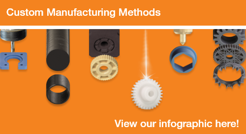
How to Use the igus® 3D-Printing CAD Configurator
A CAD configurator has many advantages. It shortens annoying recurring construction work and thus saves time and money with simple use and constant data quality.
In principle, our 3D printing CAD configurator enables a wide variety of wear-resistant parts to be implemented quickly by determining individually selected and valid product features. It is particularly important to configure a data set suitable for production for 3D printing.
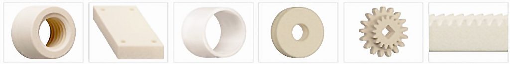
You can configure your CAD data for wear-resistant parts, such as gears, racks, plain bearings, rollers, sliding elements and threaded nuts (with trapezoidal thread), online in just 3 steps. Below, we'll use gears as an example.
1. Select component group
- Go to the overview of our 3D CAD configurator and select the component group "Gears".
- The selected CAD configurator opens and you can get started right away.
2. Create your individual 3D model
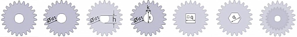
- Select the appropriate template as the basis for your component:
- Shape (hole, flattened hole, hole and key grove, inner-square, inner-hexagon) and
- Gear teeth (single or double toothing)
- Select the calculation method (tooth module or tip diameter)
- Input your specific requirements (number of teeth, gear width, shoulder width, hole diameter, etc.)
- The 360-degree view of the component is updated according to the dimensions you entered.
3. Download the CAD file or insert it directly into your own CAD software
- Select the required file format for the download and download the CAD file. To do this, press the orange download button and click "Go to Download center"
- Now, simply use the save symbol to download the individual configuration data onto your computer
- To download all configurations in a zip file, use the orange download symbol
- Alternatively, with direct insertion you can easily and conveniently insert your configured models into your CAD program and edit them there. The Click2CAD Toolbox is required for this
Repeat these steps to create other CAD configurations.
If you want to have the configured 3D model produced directly by our 3D printing service, you can upload it directly to our online tool. Please ensure that you select the STEP file format.
If you have any questions, contact an igus® here. You can also learn more about our 3D print service here and our wear-resistant 3D printing materials.