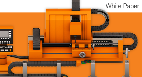


The supporting movements that decide machine tool reliability
A machine tool is bought on a short list of numbers. Positioning tolerance, surface finish, cycle time, and spindle power fill the quote and the comparison spreadsheet. Those same numbers explain less about downtime than most buyers expect.
One five-year field study of twelve machining centers sorted every recorded failure by subsystem. The spindle system came sixth, at 9.4%. The tool magazine, the electrical system, the clamping accessories, and the guards each produced more.
| Subsystem | Share of recorded failure |
|---|---|
| Hydraulic system | 18% |
| Tool magazine | 12.9% |
| Electrical system | 12.6% |
| Clamping accessories | 10.55% |
| Guard system | 10.4% |
| Spindle system | 9.4% |
| Top six subsystems combined | 3% |
| All remaining subsystems | 27% |
A machining center is full of movement that never touches the workpiece. Cables flex with every stroke. Doors slide, panels swivel, magazine chains pivot, and loaders reach into the work area between cycles. None of it appears on the spec sheet. All of it appears in service reports.
A machine down for a seized pivot is just as down as one with a spindle fault. Reliability is decided in the movements that never appear in a specification. What follows is a short survey of that motion — the four families it falls into, the one condition they share, and three questions that catch most failures early.
Which parts of a machine get reviewed, and which do not?
Follow the engineering hours through a machine build. Most of them land on the cutting process — spindle assembly, drive train, structural stiffness, thermal behavior, and the control that ties them together. That work gets simulated, reviewed by several people, and tested, because it carries the specification the machine is sold on.
Reliability numbers follow the same pattern. Mean time between failures gets calculated for the spindle assembly and the drive train, where the data exists and the stakes are visible. It rarely gets calculated for a magazine pivot or a guard guide. A machine tool behaves as a series system, though, and the shortest-lived bearing point in it sets the interval everything else gets measured against.
Supporting motion gets what is left over. Space, once the machining envelope, the chip conveyor, and the enclosure are fixed. Budget, once the cutting hardware is quoted. Review time, once the release date is close. Tight bend radii, stacked bearing points, and a bushing chosen from whatever the catalog had in stock are normal outcomes. None of those constraints reflects how much the movement matters — only when it was addressed.
By the time a sliding door binds or a magazine pin needs replacing in the field, the design conversation happened months earlier. Often it was not a conversation at all. Someone specified a bushing that matched the bore and moved on. The cheapest part in the assembly ends up carrying the availability of the machine around it.
Four kinds of movement that surround the cutting process
Supporting motion falls into four recognizable families. None of them is complicated on its own. The trouble starts when they share an assembly.
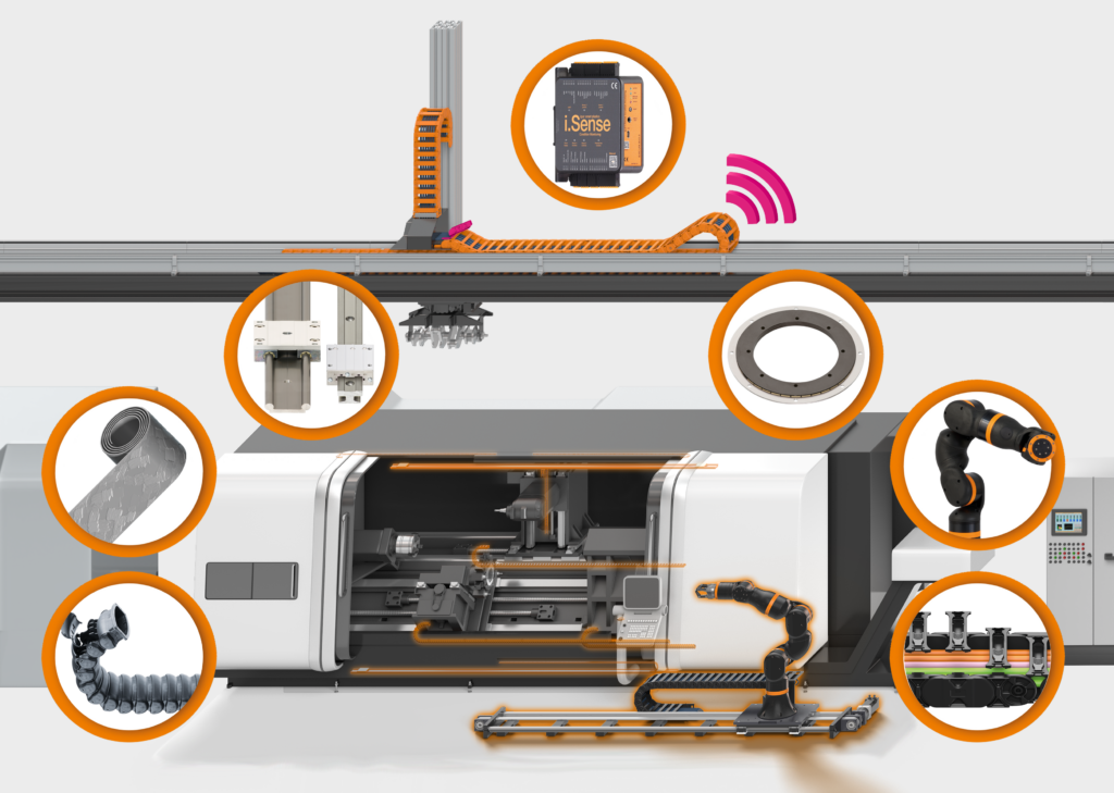
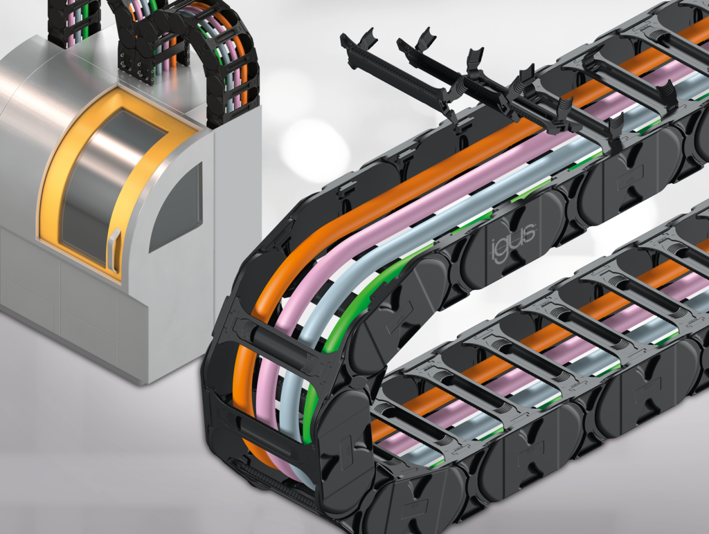
Things that carry power and media. Power, data, air, coolant, and hydraulic lines travel with every moving member of the machine. An e-chain® cable carrier guides them along the route, and chainflex® continuous-flex cables have to survive the bending that route imposes. The problem here is a motion problem — a bend radius and a fill plan — rather than a wiring problem.
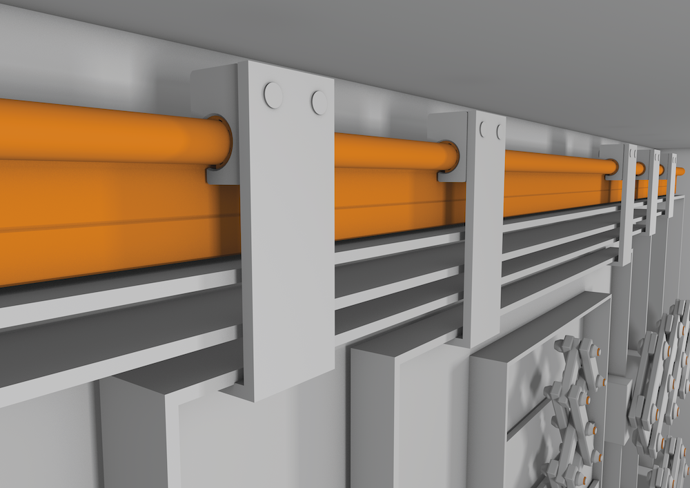
Things the operator touches. Doors, safety guards, adjustable panels, fixture clamps, and format adjustment points move every shift, usually by hand. drylin® linear bearings handle guidance in most of these places. Operating force counts as much as load capacity here, because a guard that needs two hands to move gets propped open instead.
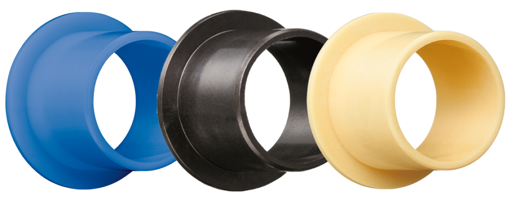
Things that pivot, swivel, and slide. Magazine chain links, hinge points, linkage ends, and small rotary joints sit scattered across the structure. iglide® plain bearings, igubal® self-aligning bearings, and xiros® polymer ball bearings each suit a different load path. Individually they cost very little. Collectively they decide how often someone opens a panel with a grease gun.
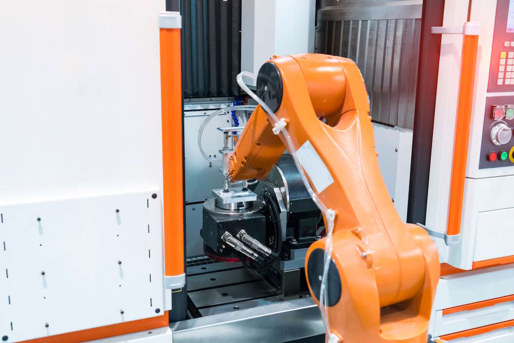
Things that feed the machine. Loading, unloading, and transport between operations. ReBeL® cobots, belt-driven linear actuators, and gantry arrangements move parts in and out of the work area. All of it runs in the same chips and coolant as the equipment inside the enclosure.
These families rarely stay separate. A chip guard door can need linear guidance for the slide, a plain bearing at the handle pivot, and a protected cable route to its safety switch. One panel, three different technologies. When any one of them binds, the operator reports a broken door, not a worn bushing, and troubleshooting starts in the wrong place.
The environment is the common denominator
Every one of those movements runs in the same conditions. Hot chips land on horizontal surfaces. Coolant and cutting oil wash across everything below the work zone. Fine grinding dust travels farther than most people expect and settles on whatever is closest. The cycling never stops.
Here is the part that surprises people. Grease is what debris sticks to. A greased rail or a greased lead screw collects chips and grinding dust until the film turns into an abrasive paste. The surface meant to reduce friction starts generating it instead. In a machining environment, lubrication is a liability.
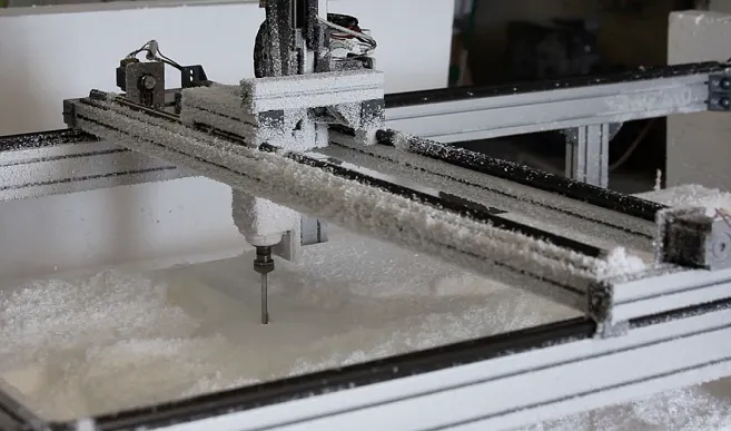
Relubrication does not fix that. It schedules it. Too little grease and metal runs on metal. Too much and the contact zone becomes a collection point for everything the machining process throws at it. Either way the machine inherits a recurring task, performed on a bearing point that is usually awkward to reach, by a technician whose hours were budgeted somewhere else.
Self-lubricating polymer bearings run dry. Solid lubricants sit inside the bearing material and transfer in microscopic amounts as the surfaces move against each other. The failure mode is removed rather than managed, so there is no lubricant film for chips to cling to and no interval to add to the plan.
Three questions worth asking before the machine is built
None of these three questions requires a simulation. All of them are easier to answer before the geometry is locked than after.
What is this movement actually doing?
Stroke or angle, load and its direction, speed, cycle count, and duty across a shift. A hinge that moves twice a shift and a hinge that moves four thousand times a shift can share a drawing and still need different parts. Duty is the number most often left blank, and it separates a bearing point that lasts the life of the machine from one that becomes a recurring spare. Duty is also the input to any MTBF estimate. Without a cycle count, a service life figure is a guess carrying a decimal point.
What does it have to survive?
Chips, coolant, cutting oil, grinding dust, wash-down chemistry, and temperature. A bearing inside the enclosure and a bearing on the loading side of the same machine do not face the same conditions. Specifying both from one line on a bill of materials is how one of them fails early. Ask the question per position, not per machine.
Can it be reached and replaced without pulling the machine apart?
This is the question skipped most often, and it costs the most when it is. A bearing point that requires removing a panel, a guard, and a cable route will not be serviced on schedule, whatever the maintenance plan says. Replacement access is part of the design, not a consequence of it. Wear parts belong where a technician can see them, reach them, and unbolt them.

Design the movement, not the part
Supporting motion is a system, not a line item on a bill of materials. The carrier, the cable, the bearing, the guide, and the access path around them behave as one moving assembly, and they fail as one. MTBF belongs to the assembly, not to any single part inside it. Specifying them separately is how a machine meets every number in its quote and still loses a shift to a part worth a few dollars.
The design goal is simple to state. Put the wear somewhere predictable, and make sure it lands in a part that unbolts. When a polymer bushing takes the wear instead of the shaft it rides on, the repair is a swap rather than a machining operation on machine structure.
For an even deeper look at the topic, the igus® white paper on motion solutions for machine tools examines it more closely. It carries selection criteria for each family of movement and documented examples from real machine builders working through these decisions on production machines.