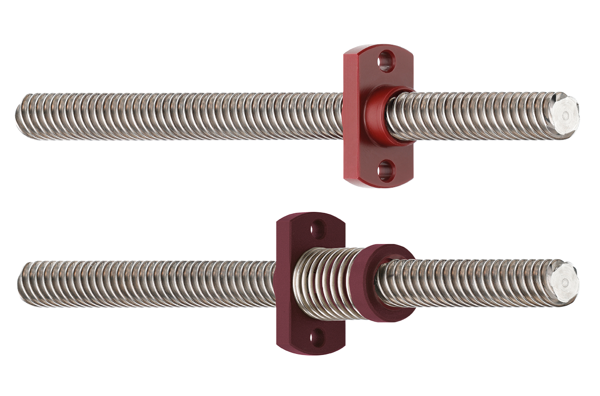


Lead screws for vertical machine tool axes: load, self-locking, and sizing
A vertical axis carrying 100 kg (220 lb) puts roughly 981 N (221 lbf) of static axial load on the lead screw before the machine accelerates or cuts. That load is always present. It is there while the axis lifts, while it lowers, and while it sits still with the motor de-energized.
A screw sized correctly for a horizontal slide can back-drive as soon as the same load is stood on end. The motor stops, gravity keeps pulling, and the nut turns the screw in reverse. Orientation changes which failure mode you are designing against.
What follows covers four decisions: how gravity rewrites the load case, what self-locking guarantees and what it does not, how lead trades speed against holding force, and how surface pressure, buckling, and critical speed bound the screw. A worked Z-axis example ties them together.

What changes when the axis is vertical?
On a horizontal axis, the linear guide carries the moving load and the screw supplies the force needed for positioning and travel. Stand that axis vertical and gravity acts along the direction of motion, so the screw carries the weight as well as moving it.
- The screw has to generate enough force to lift the load. The motor and screw must overcome gravity as well as friction, acceleration, and process forces.
- The system may need to resist back-driving. When the motor stops, gravity can drive the load downward and rotate the screw in reverse.
- Holding position becomes a requirement. The axis may need to stay put when the motor is stopped or when power is removed.
- Screw selection is critical. Lead, diameter, length, thread geometry, and friction all change how the screw behaves under load.
- Safety is a separate requirement. A self-locking screw helps prevent unwanted movement, but it should not be treated as a safety device for a suspended load.
These conditions show up on Z-axes, vertical slides, and tool positioning mechanisms that hold a head above the work area. Vertical axes are not simply horizontal axes turned 90 degrees — they become a load-bearing element rather than just a positioning one.
What happens when the motor stops?
What is self-locking?
Self-locking describes a screw and nut pairing that moves only when an external force is applied. The screw still converts rotation into linear travel, but the linear load cannot easily reverse that process and turn the screw backward
Motor off → gravity acts on load → screw resists back-driving → axis remains stationary
The effect comes from the pitch angle of the thread and the coefficient of friction between the contact surfaces. A shallower pitch angle or a higher frictional resistance produces a stronger locking effect, to the point where the nut moves only once a defined force is applied.
Self-locking behavior therefore depends on lead, thread geometry, friction, load, and operating conditions.
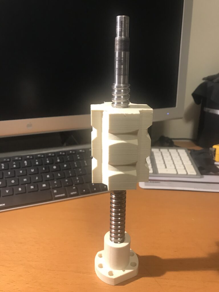
What happens with a back-drivable screw?
Change the geometry so the load can turn the screw easily and the sequence changes:
Motor off → gravity acts on load → force exceeds motor holding torque → load moves downward → nut rotates screw → screw back-drives motor
The axis does not hold position simply because the motor stopped. For some applications that is acceptable. For a vertical machine tool axis, it is a problem to solve before the machine is built.
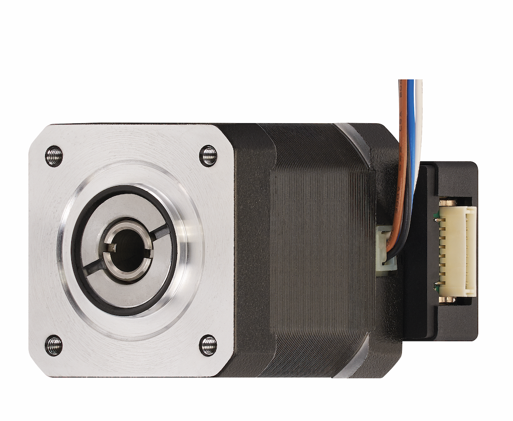
A standard igus® NEMA23 motor has a holding torque of 2 Nm (1.5 lb-ft). If the torque reflected back through the screw exceeds that figure, or if power is cut, the axis needs another way to hold, such as a motor brake or a mechanical lock.
Why self-locking has to be verified case by case
Self-locking is calculated theoretically, and the calculation rests on assumptions that shift once a real machine is running:
- Material pairing. Different nut and screw material combinations produce different coefficients of friction.
- Surface finish. Smoother contact surfaces reduce friction and weaken self-locking; rougher surfaces raise frictional resistance.
- Solid lubricants. The solid lubricants in igus materials reduce friction compared with a standard plastic and hold it consistent across the service life of the nut.
- Axial load. Under higher loads the nut presses harder against the screw, which can increase friction and strengthen the locking effect.
- Vibration. Vibration can overcome the breakaway torque produced by static friction. Kinetic friction is usually lower than static friction for the same pairing, so once movement starts it takes less to continue.
A machining center is a high-vibration environment by definition, so the theoretical figure needs confirming under real operating conditions. Note: self-locking should not be considered an alternative to a safety device. For safety-critical loads, a brake or other independent safety mechanism may still be required.
How lead trades speed for holding force
Lead determines how far the nut travels per screw revolution, and it sets the ratio between motor torque and axial force. It is the second decision after the load itself.
| Lower lead | Higher lead | |
|---|---|---|
| Torque for a given axial load | Lower | Higher |
| Resistance to back-driving | Higher | Lower |
| Linear speed | Lower | Higher |
| Screw RPM for a given speed | Higher | Lower |
Worked comparison at 1 m/min
At a required speed of 1 m/min (3.3 ft/min):
| 2 mm lead | 10 mm lead | |
|---|---|---|
| Screw speed | 500 RPM | 100 RPM |
| Mechanical advantage | Higher | Lower |
| Back-driving tendency | Lower* | Higher* |
Where the efficiency goes
Most of what a lead screw loses, it loses to friction where the nut rides the thread flank, turning motor torque into heat instead of travel. How much it loses depends mainly on the lead angle — how steeply the thread climbs around the screw — and on the friction of the screw and nut pairing.
A steeper lead angle wastes less. The nut rubs across less thread for every millimeter it travels, so high-helix screws convert more of the motor's work into motion than a fine-pitch trapezoidal screw does. However, that efficiency does not translate into lower torque. A large lead moves the nut further per turn, therefore pushing a given load takes more motor torque on a high-helix screw than a trapezoidal one.
Further reading: What is screw pitch, and how is it different from screw lead?
A high-helix screw suits applications that need speed and can supply the torque. A fine-pitch trapezoidal screw suits heavy loads, slow feeds, and positions that must hold without power.
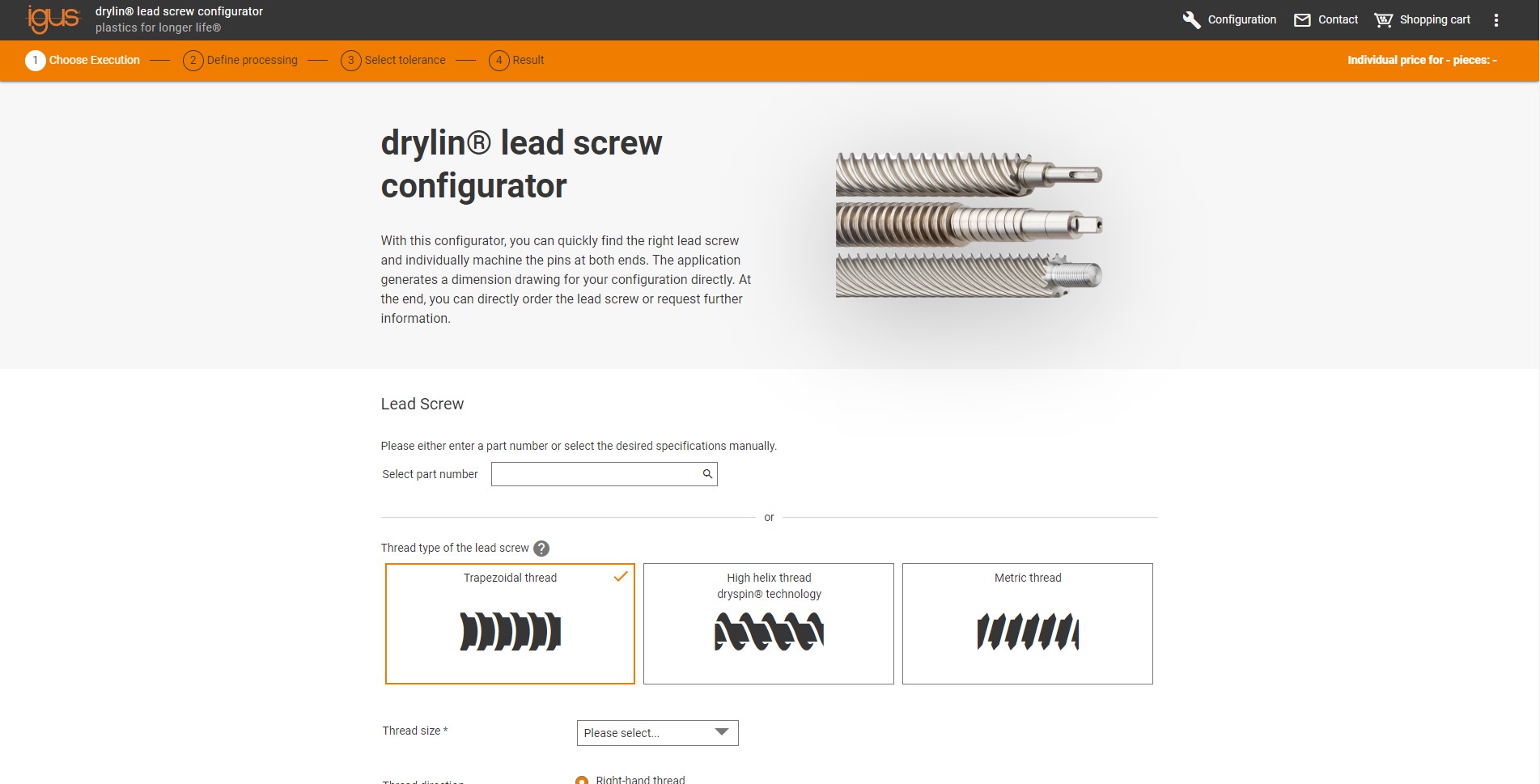
Our online lead screw configurator can help you select the correct thread size, including recommendations regarding speed limits and possible vibration and noise issues.
What actually limits load capacity
A screw's load capacity cannot be evaluated from one number. Start with the axial force, then test it against four independent limits. The lowest limit will govern the design.
Axial load
Start with the gravitational load:
F = m × g → 100 kg × 9.81 ≈ 981 N (221 lbf)
The design load must also account for acceleration, friction, external and process forces, and safety factors. On a machine tool axis, cutting forces act along the screw during the stroke, so the peak axial load is rarely the static weight alone.
Surface pressure on the nut thread
The nut thread has to carry the axial force without exceeding the allowable continuous surface pressure of the nut material. Required contact area follows directly:
Ae = Faxial / Ptol
Allowable continuous surface pressure varies by iglide® material:
| Nut material | Allowable continuous surface pressure |
|---|---|
| iglide® J | 580 psi (4.0 MPa) |
| iglide® L280 | 725 psi (5.0 MPa) |
| iglide® A180 | 508 (3.5 MPa) |
| iglide® J350 | 290 psi (2.0 MPa) |
A material with a lower allowable pressure needs more thread engagement for the same force, which means a longer nut, a larger diameter, or both. Material choice and nut geometry are one decision, not two.
pv value and duty cycle
Load and speed cannot be evaluated independently. The pv value combines surface pressure and sliding speed into one limit, reflecting how much frictional heat the polymer nut can shed. Using pv and the effective support surfaces in the dimension tables, the permissible surface speed and resulting feed rate follow for each thread size.
Standard values for drylin® plastic nuts running without lubrication, at a stroke of 500 mm (19.7 in):
| Duty cycle | pv reference |
|---|---|
| 100% | 0.08 MPa × m/s |
| 50% | 0.2 MPa × m/s |
| 10% | 0.4 MPa × m/s |
An axis that indexes a few times an hour can run harder than one cycling continuously. A correction factor applies at very short and very long strokes, so stroke length belongs in the sizing calculation.
Critical speed
Above the critical speed the screw enters resonance and begins to whip, which shows up as noise long before damage. Diameter and unsupported length set the limit, and lead sets the RPM needed for a given speed, so a long, fine-lead screw runs into critical speed first.
Change one and the others have to be rechecked. Lead screw sizing is iterative, not sequential.
Design example: a vertical Z-axis
CNC machine tool Z-axis:
- Moving mass: 100 kg (220 lb)
- Travel: 500 mm (19.7 in)
- Required speed: 100 mm/s (3.9 in/s)
- Orientation: vertical
- Requirement: resist unwanted movement when stopped
- Maintenance: no external lubrication
Step 1: Calculate the gravitational force
F = 100 kg × 9.81 m/s² ≈ 981 N (221 lbf)
This is the force required just to counteract gravity. Acceleration, friction, and external forces must be added before a screw is selected.
Step 2: Select the lead
Screw speed follows from linear speed divided by lead. Taking a required speed of 1 m/min with a 5 mm lead:
1 m/min ÷ 5 mm/rev = 3.33 rev/s = 200 RPM
The selected lead is then evaluated against motor torque, linear speed, back-driving behavior, load capacity, and screw length and critical speed. If any one of those fails, the lead changes and the others are rechecked. As a general rule of thumb, for screws with a diameter under one inch will self-lock with a lead of 5 mm or less. Screws with a greater lead at this diameter are more likely to back drive.
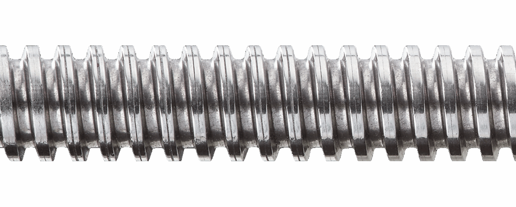
Step 3: Select the screw and nut
Where maintenance-free operation is wanted, a dryspin lead screw with an iglide polymer nut removes the need for external lubrication. The solid lubricants sit within the polymer, so there is no grease to reapply and none to migrate onto the workpiece.
Check the nut material against the surface pressure and pv figures above. At 981 N of static load, required contact area differs by more than a factor of two between iglide J350 and iglide L280.
Step 4: Decide how the axis holds position
Confirm whether the chosen pairing self-locks under the actual load, material pairing, and vibration of the machine. Where the suspended load presents a hazard, specify a brake or mechanical lock as an independent measure. This decision belongs in the specification, not in commissioning.
Eight questions to answer before you specify
- What is the moving mass?
- What axial force is required, including acceleration and process forces?
- What linear speed is required?
- What lead provides the right speed and torque balance?
- Does the application require resistance to back-driving?
- What is the screw's unsupported length?
- What RPM will the screw operate at?
- Is an independent safety mechanism required?
Worked in that order, each answer narrows the next choice.
Final takeaway
For vertical machine tool axes, lead screw selection balances load, speed, torque, and back-driving behavior. Work the numbers in order — mass, axial force, lead, then the four limits — and check the holding requirement separately from the motion requirement. A screw that moves the load correctly may still not hold it.
Getting it wrong is expensive to unpick. Across twelve machining centers tracked over five years in one field-data study, the screw and guide system took longer to repair than any other subsystem, averaging just over four hours per failure. The right screw and nut combination provides controlled, maintenance-free linear motion without nut preload or external lubrication — worth specifying deliberately rather than inheriting from the horizontal axis design next to it.