

How to Choose a Linear Actuator
Every linear actuator does the same job: convert rotary motion from a motor into controlled motion along a straight line. How it makes that conversion decides nearly everything downstream — how fast the carriage moves, how far it travels, how hard it pushes, whether it holds position when power drops, and what a technician has to touch to keep it in tolerance.
Two drive types cover most industrial applications. A screw-driven actuator turns a lead screw through a nut fixed to the carriage. A belt-driven actuator wraps a toothed belt around a driven pulley and pulls the carriage along the rail. The sections below cover what that difference does to performance, then walk through the order to work the constraints when specifying one.
What the drive mechanism changes
A screw multiplies torque before it ever reaches the load. The lead — the distance the nut advances per revolution — sets thrust and resolution together. A fine lead advances the carriage a few millimeters per turn, so motor torque acts across a long rotation for a short linear move. Small leads buy thrust and resolution, and pay for both in speed.
A belt converts through pulley circumference instead. One revolution moves the carriage the full pitch circumference of the drive pulley, which is commonly an order of magnitude more travel per turn than a screw delivers. The same motor covers ground far faster, with no mechanical advantage left over to help it push.
Mass sits in different places, too. A screw-driven actuator has to spin the entire screw, and rotational inertia climbs steeply with screw length and diameter. A belt-driven actuator spins two small pulleys and drags a light belt, so a 3,000 mm belt actuator accelerates much like a 500 mm one. A long screw fights its own inertia every time the motor reverses.
Screw-driven linear actuators
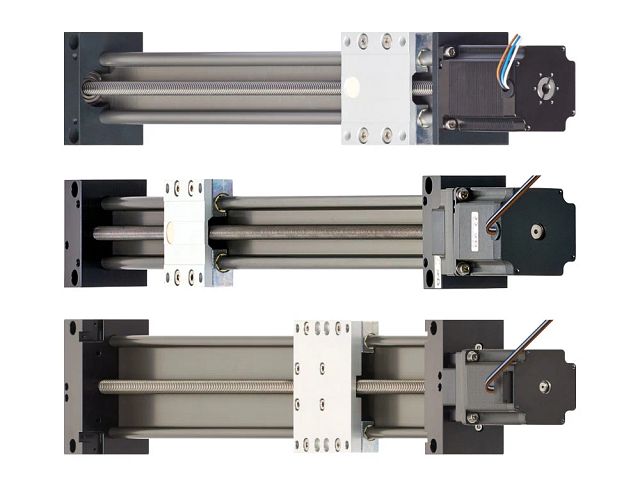
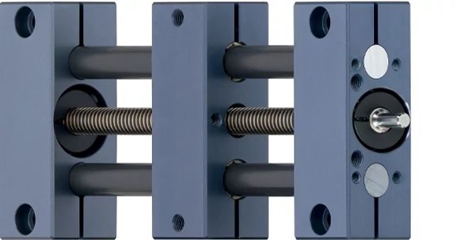
Screw drives are the answer when the load is heavy, the move is short, and the position has to be exact. drylin® screw-driven actuators run the nut and bearings on dry-running polymer liners, so the screw needs no grease and picks up no dirt.
Thrust and resolution come from the lead
Trapezoidal (low-pitch) screws sit at one end of the range. They advance a short distance per revolution, which produces high axial thrust and fine positioning resolution from a small motor. dryspin® high helix screws sit at the other end. Their steeper thread angle moves the carriage further per turn and reaches moderate speeds, at the cost of some thrust per unit of torque.
Lead selection is the first real design decision on a screw actuator, and it constrains the motor choice that follows. A format adjustment that has to hold a 100 lb load at a specific setting and a lab machine that indexes a sample tray have different answers. Pick the lead around the load and the resolution first, then size the motor to the torque that lead demands.
Critical speed sets the travel limit
Every screw has a rotational speed at which it begins to whip, and that speed drops as the screw gets longer and thinner. The limit is geometric, not a materials problem — it comes from the unsupported span between the end bearings. Once the screw approaches that speed, the shaft deflects, the motion gets noisy, and the drive loses accuracy. Critical speed is why screw travel is bounded while belts scale further.
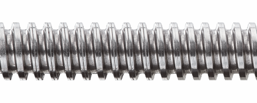
In practical terms, that puts most trapezoidal screw actuators in the range of about 1,500 mm of travel and high helix versions closer to 1,000 mm. Beyond that, the usable speed at length drops far enough that a belt drive or a rack-and-pinion drive becomes the better engineering answer.
Holding load without power
A fine-lead screw is typically self-locking: friction in the thread holds the carriage where the motor left it, with no current and no brake. That behavior matters on any vertical application, where a drive that back-drives under gravity is a safety problem, not just a positioning one. Self-locking removes the holding brake from the bill of materials and keeps the load in place through a power loss.
Where the drylin range lands
The SLW and SAW series use fully supported aluminum rails, which resist twisting better than shaft-guided designs such as the SHT. Standard SLW models suit applications under 100 RPM and manual positioning, while the SLWE-BB and SAW versions run up to 1,500 RPM depending on load and length, with SAW carrying axial loads from 6 lb to 34 lb. One family covers hand-cranked format changes and motorized continuous duty, which keeps the rest of the machine design consistent.
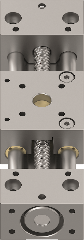
Variants handle the awkward cases. SLW-PT covers the lead screw for dirty environments, SLWT runs twin screws for independent carriage adjustment, SLWM integrates a measuring system for repeatable positioning, and XY tables stack two actuators into a compact two-axis unit.
Choose a screw-driven actuator when
- The load is vertical, or has to hold position without power
- Travel is roughly 1,500 mm or less
- Axial thrust matters more than cycle time
- Positioning resolution is fine and repeatability is critical
- The application is a format or lane adjustment rather than a continuous move
- The environment is hot, cold, corrosive, or washdown
- Low noise is a requirement
Belt-driven linear actuators
Belt drives answer the opposite problem: light loads that have to move a long way, quickly, over and over. drylin® ZLW belt-driven actuators pair a toothed belt with the same dry-running polymer liners, in a hard-anodized aluminum profile.

Speed, travel, and cycle rate
ZLW actuators handle strokes up to 3,000 mm and run comfortably in the 2 to 3 m/s range, reaching up to 5 m/s depending on load. Compare that against a motorized screw actuator: at 1,500 RPM with a 12 mm lead, the carriage moves 300 mm/s. The belt drive covers the same stroke roughly ten times faster, which is the entire reason the technology exists.
Top speed is usually the wrong number to fixate on, though. Most handling applications never reach it, because the carriage spends the whole move accelerating and decelerating. What actually determines throughput is how quickly the drive can change direction, and low moving mass is what wins short cycles. A belt actuator carries almost none.
What you give up in position control
A belt is an elastic member under tension. Under acceleration or an off-center load, the belt stretches slightly and the carriage lags where the motor thinks it is. A motor-mounted encoder cannot see that error, because it happens downstream of the measurement. Belt drives trade absolute position certainty for speed, which is a fair trade in pick-and-place and a poor one in fine adjustment work.
For most handling tasks, positioning tolerances looser than about 0.1 mm are well within reach. Belt actuators also do not self-lock, so any vertical or inclined installation needs a motor brake sized to hold the load.
Belt tension is the maintenance variable
A belt drive adds one adjustment a screw drive does not have. Tension keeps the teeth seated in the pulley grooves and holds the free span stiff enough to resist reversing loads. Too loose, and the belt climbs the tooth flank and skips, which throws off position on any indexing application. Too tight, and the excess load passes into the pulley shafts and the bearings that were never sized to carry it.
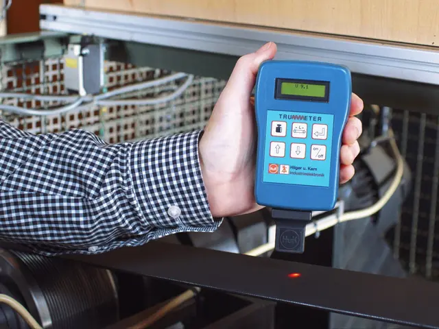
Most of a belt's stretch happens early, so a new installation is worth rechecking a day or two after commissioning and then folding into a regular maintenance interval. A sonic tension meter such as the TRUMMETER reads the vibration frequency of the plucked free span and converts it to tension in newtons or hertz, which removes operator judgment from a check that otherwise comes down to thumb pressure. Our guide to measuring belt tension compares all three field methods and when each one is appropriate, and the TRUMMETER is available on the RBTX Marketplace to add to your cart directly — no RFQ needed.
Where the drylin range lands
ZLW basic and standard models cover sizes 0630 through 1080. Opposite-drive versions move the motor to the far end where mounting space is tight, ZAW adds a cantilever design, and ZLN handles low-profile miniature applications. Environmental variants extend the same actuator into places most belt drives do not go — stainless steel and FDA-compliant builds for food processing, carbon fiber and EX versions for flour, woodworking, and paint shops, and LT and UW builds for cold storage and underwater service.
Choose a belt-driven actuator when
- Travel runs up to 3,000 mm
- Speed or cycle rate drives the machine's throughput
- The load is light and horizontal
- Positioning tolerance is looser than roughly 0.1 mm
- The installation needs a flat, low-profile envelope
- The actuator is one axis of a gantry or pick-and-place cell
Screw-driven and belt-driven side by side
| Screw-driven | Belt-driven | |
|---|---|---|
| Motion conversion | Nut advances along a thread | Toothed belt wraps a drive pulley |
| Typical travel | Up to ~1,500 mm | Up to 3,000 mm |
| Typical speed | ~300 mm/s at 1,500 RPM with a 12 mm lead | 2–3 m/s, up to 5 m/s by load |
| Axial thrust | High, set by lead and motor torque | Limited by belt tension and tooth shear |
| Holds load without power | Yes, with a self-locking lead | No, requires a motor brake |
| Positioning behavior | Rigid, repeatable, resolution set by lead | Elastic under load and acceleration |
| Moving mass | Screw inertia grows with length | Low and roughly constant with length |
| Maintenance variable | None — dry-running and grease-free | Belt tension, checked on a schedule |
| Best fit | Format adjustment, vertical lifts, precision positioning | Handling, gantries, long horizontal moves |
Working the decision in order
Most specification mistakes come from starting with speed. Speed is easy to picture and easy to quote, but it is rarely the binding constraint. Work the gates in this order instead.
Start with orientation
A vertical or inclined load narrows the field before any other requirement matters. A self-locking screw holds the carriage through a power loss on its own. A belt drive in the same position needs a brake, and that brake has to be sized, wired, and verified. Orientation decides more actuator selections than any other single factor.
Then check travel length
Past roughly 1,500 mm, critical speed starts eating into what a screw drive can usefully do. Past 3,000 mm, a belt drive runs out as well, and the answer becomes a rack-and-pinion actuator or a multi-actuator arrangement. Travel length eliminates options faster than it selects them, which makes it a useful second gate.
Then speed and cycle rate
Calculate the move you actually need, not the maximum the catalog allows. Multiply the stroke by the cycles per minute and add the acceleration and deceleration time at each end. If a screw drive at a reasonable lead clears that number, the conversation is over — the screw gives you thrust and holding force for free. If it does not, the belt drive is the option.
Then positioning tolerance
Ask where the tolerance is measured. A motor-mounted encoder reports shaft position, not carriage position, and on a belt drive those two diverge under load. If the specification is tight, either move to a screw drive or add measurement at the carriage, as the SLWM series does with an integrated measuring system.
Then duty cycle and environment
A screw nut generates friction heat proportional to load and speed, so a continuous-duty application at high load needs the thermal check that an intermittent one does not. Environment pushes the other way and often makes the call on its own: dry-running polymer bearings run in washdown, chip-filled, cold, and cleanroom conditions where a lubricated recirculating-ball system would need a wiper, a boot, or a relube schedule.

Cost belongs last, after the physics has narrowed the field to actuators that will actually work. A cheaper actuator that back-drives under load, whips at speed, or needs a brake nobody budgeted for is not the less expensive option.
Narrowing it down
The igus linear actuator configurator takes application parameters, returns configured actuators that meet them, calculates service life, and places the order in one pass — which is faster than working a catalog by hand. Every option can be ordered ready to install with drylin® E stepper and DC motors and matching motor controllers already fitted.
If the application sits near a boundary — a long vertical move, a tight tolerance at high speed, a duty cycle that looks marginal — that is the point to get a second opinion before committing to a design. Those are the cases where the specification looks fine on paper and the machine tells a different story in the plant.