The 12 most important types of gears you need to know
Gears are foundational components in countless machines, serving as the primary mechanism for transmitting power, modifying speed, and controlling motion across almost every industry. However, the world of power transmission extends far beyond the basic cogwheel. Selecting the wrong component from the many types of gears available can lead to noise, excessive wear, and even system failure.
This comprehensive guide breaks down the essential types of gears, from the everyday spur and helical varieties to specialized hypoid and worm gears, explaining precisely how each one works, their unique limitations, and where you should use each to optimize your mechanical application.
What is a gear?
Gears are an essential component of machines across near-countless industries and applications. Gears are circular mechanisms consisting of evenly spaced teeth that mesh with the teeth of other gears to transfer rotational force. Two or more gears meshed in sequence is referred to as a gear train or transmission.
How do gears work?
The primary function of all types of gears is to transfer rotational force by “meshing” with another gear. This meshing is achieved through the interlocking of the teeth of each gear, allowing force to be transferred between gears, as well as allowing changes to speed, torque, and the direction of rotation.
While gears all serve a similar primary function, there’s a large variety of gear types that all have unique design elements and methods of transferring forces. These gear types include spur gears, helical gears, gear racks, and more. Understanding the differences between the different types of gears is therefore essential to choosing the optimal gear for your application and maximizing service life and overall performance.
This article will serve as an all-in-one guide to the various types of gears available, the applications each is best suited for, and the advantages and limitations of each.
Spur gears
Spur gears have the simplest design of any of the different types of gears, consisting of evenly spaced straight teeth around the circular body of the gear. The teeth can also be cut into the interior surface of the gear — known as an internal gear — however, these will be discussed later. This makes spur gears relatively cheap and easy to produce, and therefore the most widely used type of gear.
Spur gears are particularly efficient and generate little friction thanks to the straight design of the teeth. They can be paired in a parallel axis configuration with other gears with straight teeth — namely planetary gears, internal gears, and other spur gears.
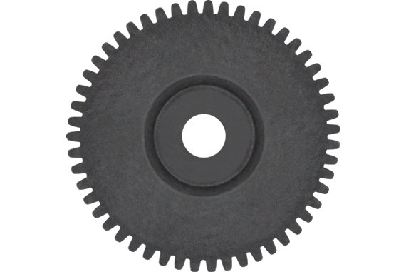
Since spur gears can only transmit force through parallel shafts, they are incapable of transmitting axial loads, instead only being capable of transmitting radial loads. Spur gears also aren’t well suited for high speeds, generating a significant level of noise due to the way the teeth mesh together during operation.
Spur gears are often used in applications such as bicycles, clocks, gear pumps and transmissions.
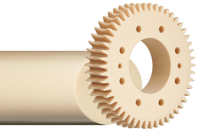
Helical gears
While similar to spur gears, helical gears have the key difference of angular teeth instead of straight teeth. Both left-handed and right-handed helical gears can be manufactured, depending on the direction the teeth are slanted. The slanted tooth design creates a larger, more gradual contact area between gears. This helps minimize noise and vibration during rapid movement. The angular teeth are also better suited for high loads.
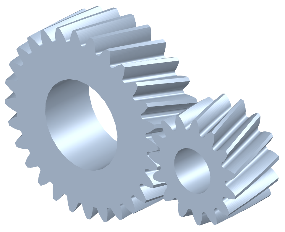
Helical gears generate axial thrust force during operation, requiring the use of thrust bearings to mitigate this force, or another option entirely such as a herringbone gear or double helical gear. Helical gears are also able to be used in non-parallel shafts due to the tooth design allowing for perpendicular gear meshing. For parallel helical gears to mesh, a left-handed and right-handed gear must be paired together, while same-handed helical gears can mesh perpendicularly (also referred to as screw gears, discussed below).
Blog: Helical gears vs spur gears & their applications
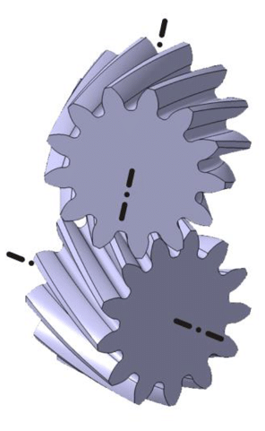
Herringbone & double helical gears
Herringbone gears and double helical gears are nearly identical, with one key difference. Each combines a left-handed and right-handed helical gear with the same twist angle. Both herringbone and double helical gears transmit motion between two parallel shafts.
The difference between herringbone gears and double helical gears lies in a groove in the center of the gear. Herringbone gears have no such groove, allowing the teeth of each helical gear to meet directly in the center, forming a V-shape from the teeth. Double helical gears, on the other hand, have this groove in the center that keeps the teeth of each side separated.
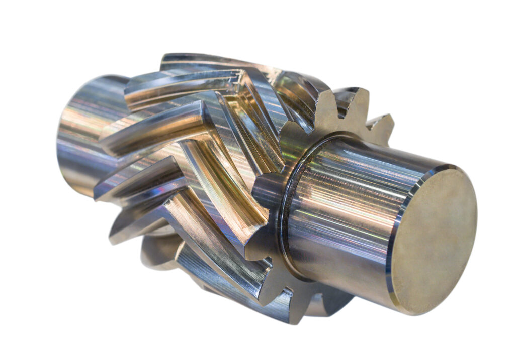
Each of these gear types are particularly difficult and expensive to manufacture, limiting their use to heavy machinery and other industrial applications. However, the combination of two opposing helical gears cancels out the thrust force generated by each, allowing the use of herringbone and double helical gears in applications where single helical gears wouldn’t be suitable.
Some common applications of herringbone and double helical gears include power transmissions, aircraft engines, and marine propulsion systems.
Screw gears
Screw gears (also called crossed helical gears) are a particular type of helical gear that are used for non-intersecting, non-parallel shafts. The gears each have a 45° twist angle. Each paired gear must be same-handed, unlike parallel helical gears where a left-handed and right-handed gear must be paired together.
The contact between screw gears is a single point unlike standard helical gears, so their load capacity is low — similar to spur gears. Screw gears are instead designed for moderate speeds and torques. Power transmission in screw gears is achieved through the sliding of tooth surfaces, making lubrication an important consideration when using screw gears — unless a self-lubricating material is used.
Screw gears aren’t suited for large loads or high speeds, and therefore tend to be used in applications like pumps or conveyors with relatively light loads and low speeds.
Rack and pinion gears
Rack and pinion gears (known more simply as rack and pinion or gear rack) consist of two elements — the rack, and the pinion. The rack is a series of equidistant teeth cut into the surface of a rod. The pinion is a circular gear that runs along the rack. A rack and pinion ultimately serves to convert rotary motion into linear motion similar to a ball screw, lead screw, or other type of linear actuator.
Blog: Ball Screw vs. Lead Screw: How to Choose the Right One
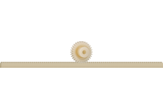
Rack and pinion gears can have either straight or helical teeth. Helical racks, much like helical gears, offer higher strength and generate less noise than straight racks. Two primary types of application exist for rack and pinions: those where the pinion is on a fixed axis and rotates with the moving gear rack, and those where the gear rack is stationary and the pinion traverses along it. One of the most popular rack and pinion applications — steering mechanisms — is within the former group.
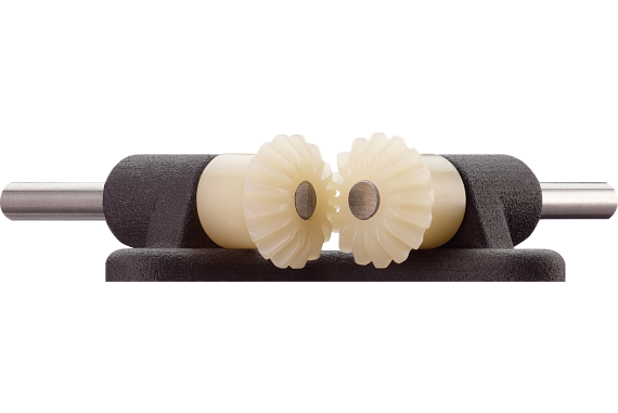
Bevel gears
Bevel gears are used for transmitting force between two intersecting shafts. The pitch surface of a bevel gear is conical, with teeth cut along the cone shape. The simplest type of bevel gear — straight bevel gears — have straight teeth. These are most often used in low-speed applications that don’t need to transmit large forces.
Bevel gears can be used anywhere from printing presses, steel plants, automobiles, and a wide variety of other industries and applications.
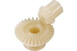
Many different variations of bevel gears exist, including spiral bevel gears, zerol bevel gears, miter gears and hypoid gears. Each operates in a similar manner and can be used within many of the same applications, but it’s vital to understand how each type of gear differs from the others.
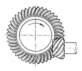
Spiral bevel gears
Spiral bevel gears also transmit force between two intersecting shafts. However, the teeth of spiral bevel gears are curved, appearing as a spiral. This tooth design enables the gears to mesh gradually, reducing noise and vibration compared to straight helical gears. Spiral bevel gears can also handle higher loads due to this tooth design.
The downside to the curved teeth of spiral bevel gears is the thrust force generated. This requires thrust bearings to counteract, increasing the total cost of the system. Additionally, spiral bevel gears are more difficult to manufacture than other bevel gear types.
Hypoid gears
Hypoid bevel gears (known also as just hypoid gears) are a specialized type of spiral bevel gear, where the two axes of the shafts are non-intersecting and non-parallel. The offset between these axes is the key difference between hypoid and spiral bevel gears; a hypoid gear with an offset of zero is the same thing as a spiral bevel gear.
The smaller gear in a hypoid gear set has a larger helix angle than the larger gear. Because of this, extremely high gear ratios can be achieved if necessary. This is particularly useful for high speed reduction with just one set of hypoid gears.
Zerol bevel gears
Zerol bevel gears are a specialized form of bevel gear developed and trademarked by The Gleason Works. Zerol bevel gears are similar to spiral bevel gears, with the exception of a 0-degree helix angle, as opposed to the 35-degree angle primarily used for spiral bevel gears.
Zerol bevel gears combine the benefits of both straight and spiral bevel gears. Zerol bevel gears do not generate significant thrust force and can be interchanged with straight bevel gears without the need to change the housing or bearings used. They also mesh gradually, so they’re more efficient and smoother than straight bevel gears — though less than spiral bevel gears.
Miter gears
Miter gears are the most wide-ranging type of bevel gear, with the capability of having a straight, spiral, or zerol tooth design. What makes a miter gear unique is its tooth ratio; both gears in a miter gear set have the same number of teeth.
When it comes to straight and zerol miter gears, a pair of the same two gears can be mated together without issue. Spiral miter gears still need to pair a left and a right-handed gear, however.
Miter gears exist solely to change the direction of transmission, as they can’t change transmission speed due to the same number of teeth on each gear. The shaft angle of miter gears can vary, though a shaft angle of 90 degrees is the most common. Miter gears designed for a non-90-degree angle are called angular miter gears.
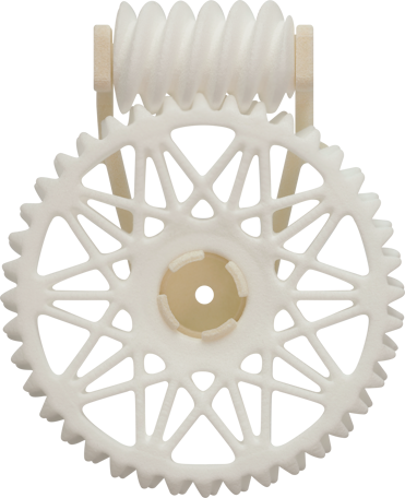
Worm gears
Worm gears, much like rack and pinions, consist of two parts: a shaft with a screw shape cut into it (the worm), and a gear that meshes with the worm (the worm wheel). Power is transferred through two non-intersecting shafts at a right angle to each other. Worm gears typically use a single point of contact and sliding motion, which generates significant friction and retains heat. To minimize wear stemming from the high amounts of friction, a harder material should be used for the worm than the worm wheel.
A major difficulty with the sliding motion of worm gears is lubrication. It’s difficult to adequately lubricate worm gears, and specialized lubricants are required which can further hinder lubrication efforts, though a self-lubricating plastic worm wheel can make this process simpler.
Worm gears are ideal in applications where noise needs to be minimized, or where a compact solution is desired. Some of the most common worm gear applications are within stringed instruments for tuning, conveyor systems, and elevators.
Internal gears
Internal gears are a type of gear mechanism characterized by teeth cut into the inner circumference of a hollow cylinder or cone, unlike external gears, which have teeth on the outer surface. Internal gears mesh with external gears to transfer rotational motion and torque.
One significant difference between internal and external gears lies in their applications and design intricacies. Internal gears are often employed in scenarios where space constraints or specific engineering requirements necessitate a compact gear arrangement. Their unique configuration allows for smoother operation and can provide better load distribution compared to external gears in certain applications.
Common applications of internal gears include planetary gear systems, where they serve as integral components in reduction gearboxes, providing speed variation and transmitting torque efficiently. They are also found in various automotive transmissions, especially in automatic transmissions, where their compact design enables efficient power transfer within a confined space. Additionally, internal gears are utilized in industrial machinery such as pumps, where their compact design and precise meshing facilitate reliable operation in demanding environments.
Webinar: Self-lubricating gears for the automotive industry
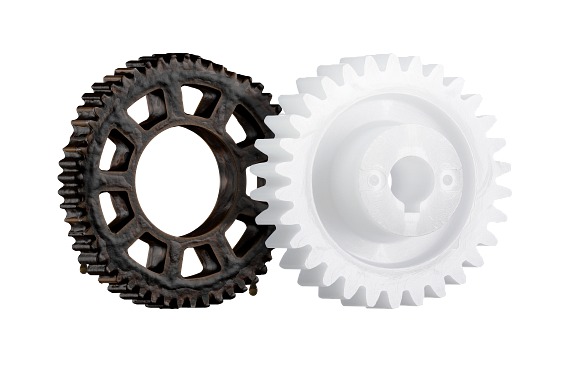
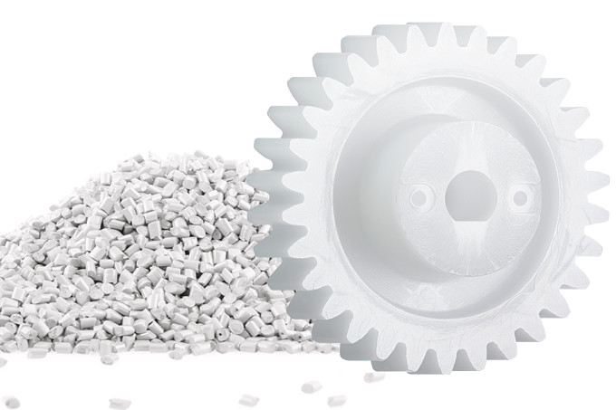
Gear materials
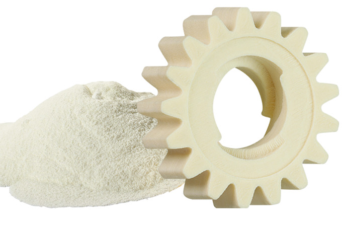
While understanding the right type of gear for your application is important, equally important is choosing the right material as well. Most often metals like steel, brass or aluminum are used. However, self-lubricating plastics are a viable — and often superior — alternative for most applications, due to their significantly lower production and maintenance costs, resistance to corrosion and chemicals, and lightweight composition.
As previously mentioned, proper lubrication can be difficult to achieve in screw and worm gears in particular. Without proper lubrication, these gears are sure to experience significant wear and a reduced service life. Self-lubricating plastics completely solve this issue by evenly dispensing lubricants during operation, ensuring a constant layer of lubrication is maintained for optimal performance.
Learn more: Plastic gears vs metal gears: Which is the better option?
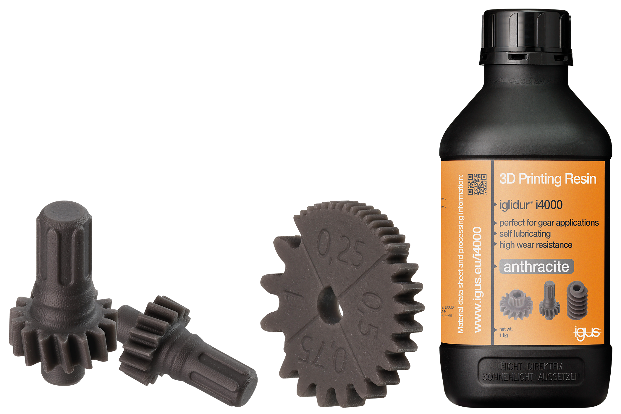
Another advantage of choosing plastics for your gears is the availability of custom manufacturing methods. Custom plastic gears can be injection molded, 3D printed, and machined depending upon the requirements of your application. Additionally, materials designed for FDA-compliance, high-temperature resistance, electrostatic dissipation and more are all available.
Tribologically optimized plastic gears from igus®
As discussed, self-lubricating plastics are an excellent option for a majority of gear applications and are available with a wide array of additional properties as needed. If you’re looking for a supplier that produces gears from these plastics, then look no further than igus.
igus uses three main manufacturing methods to produce plastic gears: injection molding, 3D printing and CNC machining. Spur gears, bevel gears, and gear racks are all produced via injection molding and available from stock. Various gear ratios, modules, and lengths are available for each of these types of gears.
The 3D printed and machined gears from igus are custom solutions, opening up the possibility of other types of gears being produced beyond the standard three injection molded offerings. These gears can be customized to meet specific application requirements, including weight, tooth shape, transmission ratio, and more. 3D printed options include SLS, FDM, and DLP printed gears.
Conclusion
The world of gears is deceptively complicated, and the wide range of options can overwhelm even seasoned engineers and designers. Hopefully this article has helped narrow down these options and made the selection process simpler. If you still have questions or concerns about selecting or implementing gears in your application, check out the resources below!
Frequently Asked Questions
A gear is a circular disc with teeth that run around its circumference. Gears are used to transmit motion or force to another gear or a chain, and two or more gears combined form a gear transmission.
The most common type of gear is the spur gear, also known as a cylindrical gear. They have straight teeth and are simple to manufacture, making them widely used.
While similar, helical gears have angled teeth instead of the straight teeth found on spur gears. This angled design allows helical gears to operate more smoothly and quietly and to handle higher loads, but they also generate an axial thrust force that must be managed.
The axes of bevel gears are typically at a 90° angle to each other and intersect. Their teeth are located on a truncated cone shape, allowing them to transmit motion between non-parallel shafts.
A worm gear consists of a helical worm and a worm wheel. They are known for having a very high transmission ratio and operating quietly, making them useful in applications where a high gear ratio is needed, such as in conveyor systems.
A gear rack is a linear machine element with teeth. When paired with a spur gear, it forms a rack and pinion system that converts rotational motion into linear motion or vice versa.
A hypoid gear is a type of spiral bevel gear with a key difference: its axes do not intersect. The offset of the smaller pinion gear allows for a larger diameter and greater tooth contact, enabling it to handle higher torque and provide a smoother, quieter operation.
Both herringbone and double helical gears combine left-handed and right-handed helical gears to eliminate axial thrust. The difference is that herringbone gears have no groove between the teeth, while double helical gears do.