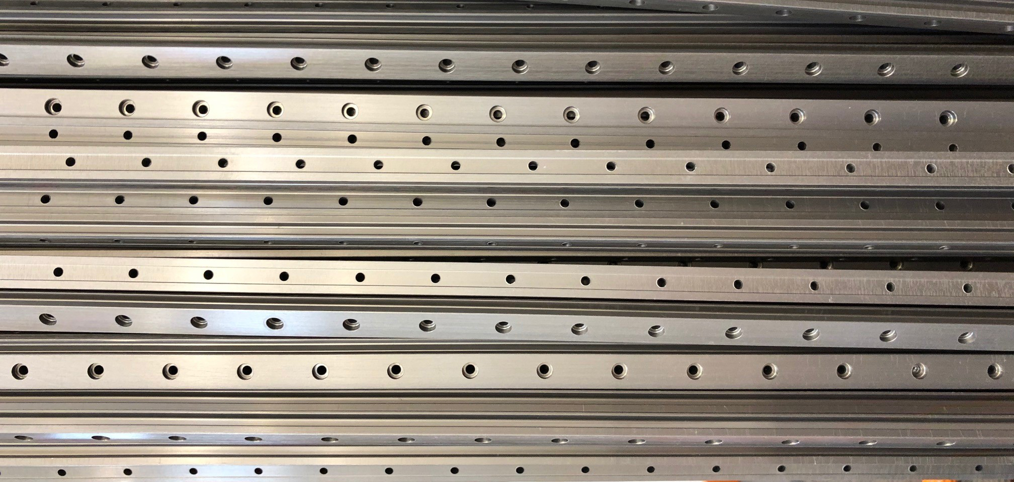
Why are there color variations between extruded aluminum linear rails and shafting?
 We get this question a lot, and when I say we get it, I mean, we get it—we understand. Let's say that you are designing a piece of equipment and the linear bearing systems involved are very prominent to your customers. You receive one lot of rails from your supplier, and they are all made from the same deep, dark-brown material. A month later, your receiving department puts a new lot of rails in stock, and then someone on your sales, marketing, or management team asks you, “why do these look different and much lighter in color?” You may now have a single machine or piece of equipment that has two different colored linear rail systems on it. Here, we hope to provide you with an understanding regarding the technical reasons for this, and then possible solutions if you absolutely need the same finished look every time.
The Case for Aluminum Extrusions
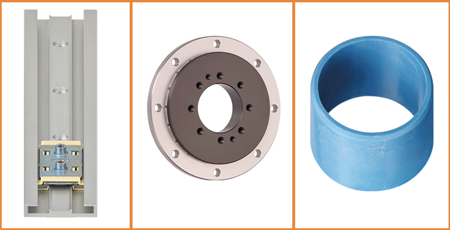
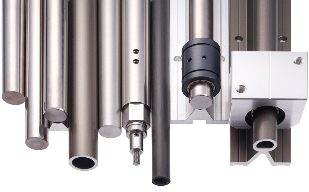
Linear plain bearings, like drylin®, often run on extruded aluminum shapes that are made from 6060-T66 and 6063-T6 tempered alloys. Although sliding plain bearings are commonly used on centerless-ground carbon and stainless steel precision alloys, they offer very complimentary benefits when combined with aluminum guide rails. These aluminum extrusions offer lighter weight, lower-cost, corrosion-resistance, and better heat dissipation for reduced frictional heat build-up as well as being easier to machine than hardened steel. We work with plenty of machine shops who refuse to drill into a steel or stainless shaft with a Rockwell hardness of RC50-65, but will machine hard anodize aluminum all day long.
The anodize finish for a linear plain bearing system must also meet a certain criteria that structural aluminum components do not necessarily have to meet—proper surface roughness must be maintained to ensure that the wear and frictional properties of the sliding bearing are optimized and consistent from lot to lot. Additionally, the outer diameter of the rail is integral in ensuring that the least amount of clearance exists between the rail and the bearing so that the precision of the overall system is as optimal as possible.
How About an Example?
Let’s say we are looking at a nominal 10mm ID bearing, and it’s on a 10mm OD guide rail. With plain bearings, we need to make sure that there is always clearance between the two parts so that we avoid potential binding. If we have a 10mm nominal bearing dimension, we want to ensure that the guide rail NEVER exceeds 10.00mm so that it does not interfere with the bearing ID and cause interference. This seems easy… until you factor in that the hard anodize that we are going to apply afterwards will result in an additional buildup of up to 0.05mm. So, if we extruded a rail at 9.98mm and applied the 0.05mm buildup of anodic layer, we would easily, or at least theoretically easily, have an OD of 10.03mm and a bearing ID of say, 10.02m—#binding.
Anodize This, Anodize That
The igus® callout for a WS-10 guide rail in the catalog is 10.0mm +0/-0.1 and in order to ensure that the max buildup of anodize will not negatively impact the bearing fit, we purposely undersize the rails from the extrusion and play with how long the parts are anodized so that the rails get as close to 10.00mm as possible—the goal being to reduce the clearance of the overall bearing system. If a part comes off of the extrusion press at the high end of the tolerance, we will apply the least amount of anodize controlled by the anodize spec on the drawing (often, Mil-A-8625F Typ III Class 1, or a similar EU specification). This results in a rail that is lighter in color, yet still meets the quality spec of the anodize thickness. Conversely, if we receive a part from the extruder that is close to the lower-end of the extrusion tolerance, we will leave the parts in the tank longer to build it back up—again, as close to the 10.00mm nominal as possible, which will result in a much darker color. It should also be noted that there may be color variations due from the anodize tank alone, making it even more difficult to control the color.
The anodize thickness has no affect upon the bearing lifetime, and the reason that we use a lot of hard anodize is because linear guides like ours are often used in outdoor or factory settings where you would want good abrasion-resistance against damage caused by the environment. The color of the rails does not matter—technically.
So, what if you want consistent rail color lot after lot?
The best solution to achieve a consistent rail color is to use a CLEAR anodize rail system that is controlled by a Mil-A-8625 Type II Class I spec—or again, similar EU standard (for a list of the new igus® products that include this option, click here) If you do choose this option, it is important to understand that there could potentially be more clearance between the carriage and the rail due to the fact that clear anodize has significantly less build-up than hard anodize. Small pro tip—you should consider bearings with preload, adjustable, or low-clearance liners.
Although I may not be an expert in regard to every single aspect of the anodize process, I have learned a lot from exhaustively working with linear bearing technology over the last twenty years. One thing that I have learned for certain is that color variations between your linear rails are unavoidable, but they occur for good reason—to give you the least amount of clearance within your overall plain bearing system. So, next time you notice several lots of differently colored rails, or a lighter rail and a darker rail being used within one system, rest assured knowing that this is all by design.
For more information about shafts or linear bearings, please feel free to contact Matt Mowry, drylin® Product Manager, here.